Announcement

Collapse
No announcement yet.

amp meter wiring

Collapse
X
 
  • Filter
  • Time
  • Show
Clear All
new posts

  • Electrical: amp meter wiring

    I have a 55 champion that the previous owner started converting to 12 volt and negative ground. I am now trying to correct a lot of bad wiring. I know the + and - need to be reversed on the ammeter but I have 3 or 4 wires on the + side and one on the negative side. Question is do I move all the + wires to negative and the one negative to the + side. Thanks for the help.

    Lee
    hopefully soon to be on the road :-)

  • #2
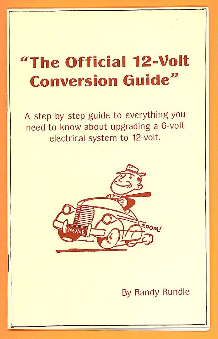
    Lee, if you are trying to finish a conversion to 12-volt, negative ground, buy a copy of Randy Rundle's 12-Volt Conversion Guide advertised in the literature section of every Turning Wheels. It is an excellent book and will answer many questions.

    It sounds like the PO was trying to use one ammeter stud as a pick-up point for accessory power. That's not a good idea. Leave the ammeter with one "in" and one "out" wire and pick up power for accessories via a fusible link off the starter relay, battery cable stud. BP

    Comment


    • #3
      You might as well check all the wiring. It's likely that the PO messed up more than one part of the job.

      For some reason, a large percentage of mechanics are completely dumbfounded when dealing with electricity and wiring. There have been a number of requests on this forum for 6 to 12 volt conversion advice. Analyzing the questions shows that the would be convertor/mechanic/improver really has no concept whatsoever of how the job can be accomplished.

      It might help to get a schematic of a 56 Champion in addition to your 55 schematic.

      Comment


      • #4
        "Don't leave home without it...."


        BP

        Comment


        • #5
          I'm not so sure anything is out of place...did a real quick check of my 54 wiring diagram shows 3 wires coming off of the positive post of the ammeter, plus a 4th if you include the power wire comming off the positive post to power the fog lights.... not wearing my glasses right now, but point being that my factory wiring diagram has multiple wires coming off of the postive ammeter post. Best get a proper wiring diagram and trace the wires to be sure. Regards, Junior.
          [SIGPIC][/SIGPIC]
          1954 C5 Hamilton car.

          Comment


          • #6
            Yep you are right Greg (Junior), all of the load was factory wired to come off of the output side (Right) of the Ammeter for a reason, that way the incoming power from the Solenoid (-) the outgoing load will show the correct amount of charge going back into the Battery. I happen to like to know the actual amount of charge.

            Nowadays everyone thinks that is old school and wrong and they want a useless Volt Meter, to each his own I guess. I prefer to know INSTANTLY if I am no longer getting a charge to finding that the voltage is already low and it's too late, the battery has little life left.


            I know they think the old way is a fire/short/accident waiting to happen but in 50 years driving them and being around them I have NEVER heard of that happening.
            The best way to improve it is to install a plug-in easy to change FUSE in the Power Wire from the Solenoid to the Ammeter.

            So the answer to the original question is yes, that is how it should be, BUT it does
            NOT need reversing because there is no (+) and (-) terminal on an Ammeter just in and out, reversing the Battery posts takes care of it, just reverse the Coil wires or buy a new Coil if you wish but they are rated by OHMs resistance not voltage so either works if you install a "Start" circuit Ignition wire and Solenoid and the resister circuit in the "Run" circuit per the '56 Wiring Dia.

            You will of course need to replace the Wiper Motor, Def. Fan Motor, Heater Fan Motor, all bulbs and seal beams and the horns should be changed but will just pull more current, be extra loud and with little use may last a while.

            Then there are the Temp. and Fuel Gauges which need to be changed or by-passed and use 12V ones under the dash. Disconnect the Radio, use a 12V one under the seat or in the glove box.
            Last edited by StudeRich; 02-16-2013, 02:01 AM.
            [COLOR=#3399cc][B][FONT=Georgia][SIZE=20px]StudeRich [/SIZE][/FONT][/B][/COLOR]
            [SIZE=11px][FONT=Georgia][B][COLOR=#800080]Second Generation Stude Driver,
            Proud '54 Starliner Owner
            SDC Member Since 1967[/COLOR][/B][/FONT][/SIZE]

            Comment


            • #7
              The ampmeter is a two function meter one function is montering the alternator/generator function, a power supply terminal for the lighting system and a power supply terminal for the rest of the remainder of the vehicle through the main hot terminal on the ignition switch. The ampmeter is identified with a + and - however it is in series with the ignition switch ie in and out and not + or -. However your battery is connected beit neg or pos to ground that same connection is made at your ignition switch it just goes through the ampmeter. The other side of the ampmeter terminal opposite to the battery ground supplies power to the lighting system and eventually back to ground and the other function monitors the charging system and back to ground I hope this is not too confusing Dave British Columbia

              Comment


              • #8
                Ok, I left the wires where they were and it appears that everything works EXCEPT it always shows a discharge. I went back to Randy Rundles book and it says to reverse the wires so that is what I did. Everything still works but now it shaows the alternator is charging the battery. I want to thank everyone for their input as I am learning more all the time, not bad for an old guy like me. Thanks again to everyone for the help.

                Lee

                Comment

                Working...
                X