Announcement

Collapse
No announcement yet.

Installing power/dual master cylinder on 2R5 trucks

Collapse
X
 
  • Filter
  • Time
  • Show
Clear All
new posts

  • Brakes: Installing power/dual master cylinder on 2R5 trucks

    I recently installed a power brake unit with dual master cylinder on the 1952 Studebaker Camper that i sold last year. The new owner wanted to upgrade the brakes as he plans to have his family member use the truck. I will take the next few days to post the pictures with comments that show you just how easy this was. I was actually surprised that it wasn't a major ordeal. It took me 23 hours of fabricating and that was working at a leisurely pace. I will tell you that there were several pieces that I had to make twice. I am not a pro fabricator so I have to make a part and fit it in place and then see if it works. I will also share the part numbers and sources for the needed parts. I can tell you that the truck stops like a newer model truck with no lock up or other issues. The pedal effort is light but not scary. The pedal travel before you feel engagement is about 1". The owner took it for a test drive and didn't want to come home he was enjoying himself too much.

    In keeping with making sure you understand the complete scope of this project I can tell you that there are two things that I would do differently on the next one. I would angle the master cylinder down at the back by a few degrees to give a little more clearance for the clutch linkage and master cylinder cap. We will also be changing the angle of the brake pedal as it is still a little too low compared to the clutch pedal. Just enough to make it uncomfortable on a long trip I think. We might take it on a trip before we make that change. Overall this is a great upgrade and highly recommended. I will probably be doing this to the 1947 truck that I will be working on this winter. I also have ordered the unit to be installed on my 1959 Silver Hawk that I am currently working on.

    Tonight I will post some pictures of the completed unit'
    Dan


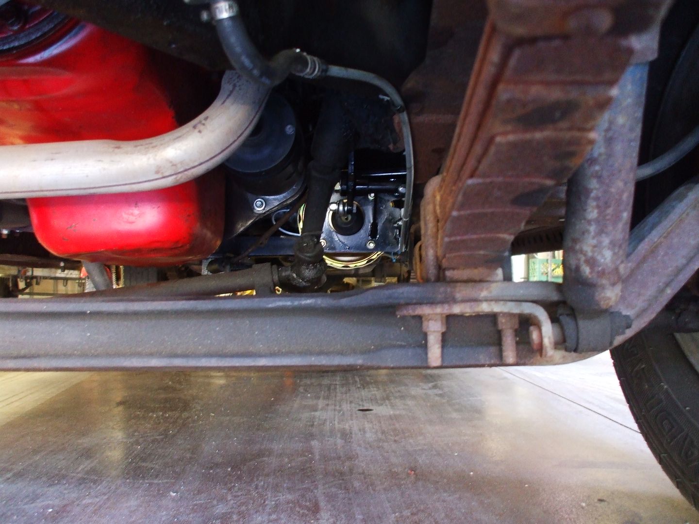
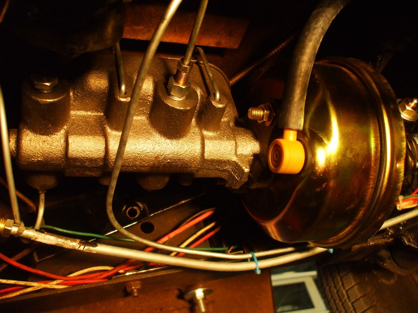
    That last picture was taken before the clutch return spring bracket was fabricated and the wiring had not been finished but you get the idea. tomorrow night I will list the parts that were used to make this happen.

  • #2
    Thanks! Dan, for this info and answering several other questions, in detail, in the past. Your moving up fast,
    on my list of S. S. (Studebaker Superheros)
    My 1st car. "A TRANSTAR"

    Starliner
    sigpic
    Somewhere between Culture and Agriculture
    in the Geographic center of Tennessee

    Comment


    • #3
      Sorry about last night I didn't have anything left by the time I got home. So the basic item used was a Speedway Motors universal pedal/booster/master assembly.

      It comes with everything that is needed to mount the unit and then you just have to plumb it into your brake system. One word of caution: do not use the bolts that are supplied with the kit. Although they work I found that they could not be torqued to US torque specs with stripping out. That tells me they are probably China knock offs. Even Ace or OSH grade 5 bolts can be torqued with no issues. The extra bracket (spacer) will not work with a manual transmission equipped truck. It interferes with the clutch linkage. One very nice feature of this kit sis the fact that the master cylinder has outlets on both sides of the master. That allows you to plumb it into your brake system easier. It comes with plugs for the two holes you might not use. My original plan was to use one of the extra holes for the brake light switch but I could not find a fitting that went from the master cylinder thread size to 1/8th inch pipe. So I added a "t" fitting to house the switch. The term universal is accurate but I found that it was close enough that you could fabricate it to fit the 2R5 body and frame. I would love to do another one ads the things I learned on this one would allow for a much faster and cleaner installation. The 23 hours it too includes four hours rebuilding, cleaning and painting the clutch linkage. The truck only has a few miles on it but it is 62 years old and the linkage had seem some use. Here are the part numbers for thee rest of the items that were used during this project:
      1--Standard Ignition SLS 27 Stop Light Switch
      2--123300 Edelmann brass fittings
      2--124320 " " "
      1--120600 " " "
      1--203200 " " "
      2--258350 " " "
      1--258302 " " "
      1--731460 " " " This is a 90 degree Push Loc fitting for the hose to manifold connection
      1--BL360 Master Parts 3/16" X 60" steel brake line
      6 feet of Dayco 80094 Power Brake Hose (rubber)
      I also re-routed the fuel line and used a 5/16" X 60" steel line, a 5/16" steel fuel filter and some 5/16" rubber hose and clamps for that part of the project.

      Comment


      • #4
        I failed to take a picture before I started taking it all apart but since you will be doing this you know what it looks like now. Here is a picture after it was all torn down.

        You will note that due to the fact the truck once had a Ford 390 V8 cobbled into it the cross member that the bellhousing mounts bolted to was cut out. I too the time to cut off the two inch piece that was sticking out as it tended to be an skin cutter. At first I also thought it might be in the way of the installation but as time went on I saw that it would not have come into play at all. Here is a refresher picture of the truck:

        More in the next few days.
        Last edited by SilverHawkDan; 08-31-2014, 08:20 PM.

        Comment


        • #5
          Removing the clutch linkage required the removal of the frame to body mount, The main bolt, a 7/16" bolt had to be snapped in two to remove. The amount of dirt and rust that fell out of the mount was eye opening. There were two holes in the clutch linkage support brackets that needed to be welded up and sized to the clutch pivot pin. The clutch pivot pin bolt broke off when I tried to remove it. So I had to weld a new bolt to it. I used a 1/2" grade 8 bolt for that repair. Since it was no longer going to support the brake pedal pivot I was able to use the part of the pin that was not grooved for the clutch pedal pivot. After it was all installed I cut the excess off and drilled the hole for the cotter pin. I used washers to remove the play between the support bracket. If you don't remove the play there will be a clicking noise as the bracket gets pushed out when the clutch pedal is depressed and released.

          After everything was wire brushed and clean up it was time for some paint

          Using new grade 5 bolts the clutch linkage and body mount were installed. I used a fiberous grease on the pivot pin and the bushing for the clutch arm support. After it was all installed a liberal amount of grease was pumped into the clutch pivot zerk fitting.
          With that completed I held the power brake unit up to see where it would best fit and operate. I put the pedal arm through the hole in the floor and checked for the travel path and stroke to see if everything would fit. The first thing that I discovered was the pedal arm would need to be modified as it pointed at the floor. So I cut the arm at the top and measured for the two mounting plates that would hold the mounting bracket.

          With that part removed I was able to hold the assembly up and figure out where the mounting plates would fit. I used 2" X 3/16" strap steel for the brackets. I welded the bolts to the plates to make installation easier. Here is a photo of the brackets installed and painted.

          I had to make sure the mounting bracket would clear the clutch linkage and by using 2" strap it left room for servicing the clutch linkage in the future if needed. So tomorrow I will post the pictures of the mounting bracket install and the rest of the set up. Stay tuned.

          Comment

          Working...
          X