Announcement

Collapse
No announcement yet.

+ & - on the coil...

Collapse
X
 
  • Filter
  • Time
  • Show
Clear All
new posts

  • Electrical: + & - on the coil...

    I'm going from -55 Studebaker Champion 6v pos. ground to -77 & -89 Mopar 12v neg. ground.

    While doing so & following the electrical diagrams (& I've NEVER been good with electrix!) I suddenly wonder:
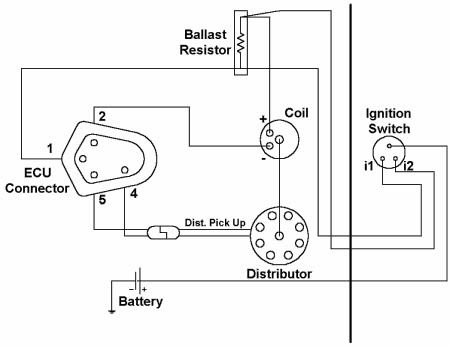
    On the original system there's only one (1) wire from the coil...
    But on the new system there's two (2), plus (+) AND minus (-)...
    So how to connect?

    & I also wonder how to get the ignition-lock out from the dashboard.
    Last edited by Noxnabaker; 12-29-2012, 02:10 PM.

  • #2
    Sounds kinda confusing on the coils. Picture might help. If I understand you right, somethings wrong. The original coil should have two wires. On the switch, reach behind the dash and push the switch toward the dash (spring loaded) then turn the ring on the dash to unlock. Or is it the key and cylinder you are trying to remove?

    P S Need to consider a shop manual,

    Comment


    • #3
      For the 12v neg ground coil, the negative post should be connected to the points in the distributor, or lead for electric ignition. The positive should go to the ignition switch. There may be a a resistor in the positive wire.
      Pat Dilling
      Olivehurst, CA
      Custom '53 Starlight aka STU COOL


      LS1 Engine Swap Journal: http://www.hotrodders.com/forum/jour...ournalid=33611

      Comment


      • #4
        The Second (+) wire at the Coil is the resister bi-pass wire to the "I" Term. on the two small wire 12V Solenoid that you should have replaced. These are usually Green or Green with a Black tracer.

        The other wire can go to a external resister or be a Pink resistence wire to the "Ign. term of the Ign. Switch.
        The 12 Volt ignition system cars start on 12V and run on 8-10 Volts.

        I would push in on the face of the dash on the chrome bezel to lock it into it's keyway notch, and turn the switch from the back while pushing in on it, 1/4 turn counterclockwise from the back should unlock it from the dash.

        Removing the Key Cyl. from the switch is done with the correct key in the lock, pushing in on the small brass "Pin" through the hole on the side of the switch.

        Be sure to check that pot metal Bezel for good strong lock tabs on BOTH sides, replacement Unbreakable Aluminum ones are available from Studebaker Vendors at:
        http://studebakervenders.com

        These have always been a short/fire risk because on most Studes. the "Hot" Batt. lead will touch the metal dash frame even on a fiberglass Hawk dash when the weak Bezels break which is often.
        Last edited by StudeRich; 12-29-2012, 04:35 PM.
        StudeRich
        Second Generation Stude Driver,
        Proud '54 Starliner Owner
        SDC Member Since 1967

        Comment


        • #5
          Hmm... yeah, the coil should have 2 connections & it probably does/did, I don't know what I've seen, so it's back to the garage!

          & it's the complete lock I wanna get of so now I'll try that too.

          Thanx a heap!

          Comment


          • #6
            Ignition 101

            Think of it this way.
            The current is always going toward a ground.
            The coil is 'inline' between the power supply and the ground switch (the distributor).
            When the points are closed, the current just goes to ground, which it wants to do.
            When the points open up, the current, still searching for the easiest ground, goes for the next easiest path.
            The coil secondary wire to the plugs (via the distributor cap).
            It goes through the coil transformer windings and out the coil secondary wire to the plugs.

            So, the current flow is always from positive to negative (on a negative ground system after 1956).
            That means the power comes into the + side of the coil and out the - side (points closed), and out the coil wire (points open).

            Points will 'cook' if given too much voltage all the time, so a resistor is usually added to hold the voltage down.
            That's where a ballast resistor (usually ceramic) is used. Sometimes a 'resistor wire' is used.
            But... Reducing the voltage 'all the time' makes it hard to start.
            So a second 12v supply wire is added, that bybasses the resistor.
            This second 12v supply is only 'hot' when the crank circuit is active, so it is usually tied to the ignition key 'start' terminal.
            The higher voltage, only during cranking, helps start the engine easier.

            There are also ignition systems that do not have an 'external' ballast resistor.
            That type of ignition system has the ballast restistor built into the coil itself.
            The coil label needs to be checked when replacing one so the correct style gets put on..

            HTIH
            Jeff
            HTIH (Hope The Info Helps)

            Jeff


            Get your facts first, and then you can distort them as much as you please. Mark Twain


            Note: SDC# 070190 (and earlier...)

            Comment


            • #7
              This is a 1955 car.
              The resistor and bypass wire were not used than.
              Robert Kapteyn

              Comment


              • #8
                Yep, the car is from -55 but the engine, gearbox & rear axle is from -77 & -89, & it's all Mopar = electronic ignition since -73.

                & I'm quite imperesed 'bout Studebaker's egnition-lock's fastening! SoI think I've managed to solve the problem, the only thing that confused me was that the white-with-red-tracer that goes down to the starter was opposite to where it shows on the diagram...

                & so I'm showing the original wire-diagram, the Mopar connecting-diagram + the module itself if someone might be interested even thou it's not Chevy-stuff...

                Click image for larger version

Name:	mopar_orange_ignition_box.jpg
Views:	1
Size:	61.6 KB
ID:	1676476Click image for larger version

Name:	55.Studebaker-Wire-Diagram.jpg
Views:	2
Size:	90.4 KB
ID:	1676477

                Comment


                • #9
                  No... for some reason that's totally clear to my computer but not to me the Mopar connection-plan didn't come up, so here I go again:

                  Click image for larger version

Name:	7131.jpg
Views:	1
Size:	10.6 KB
ID:	1676478

                  Comment


                  • #10
                    But, as stated by the original post, the car has been converted to 12v negative ground.
                    So, if he does not have them, he will need to add them.


                    Originally posted by rkapteyn View Post
                    This is a 1955 car.
                    The resistor and bypass wire were not used than.
                    Robert Kapteyn
                    HTIH (Hope The Info Helps)

                    Jeff


                    Get your facts first, and then you can distort them as much as you please. Mark Twain


                    Note: SDC# 070190 (and earlier...)

                    Comment


                    • #11

                      Comment


                      • #12
                        Yes ST2DES, I've got that one also, I've been google'ing & copied to my desktop.
                        (...Are you also a little bit "Moparistic"?)

                        Comment


                        • #13
                          Now I've been on to the (as I thought) last bits of this electrical brain-punching for a week, feeling good that it all comes together... I thought it did.
                          But I get confused!

                          & I wonder if anyone else have been looking at the original diagram & on the car's ignition-lock & found that the white with red tracer has changed place with the black with green tracer? ...On the plan it shows that the black-green goes between the coil & the lonely term on the switch & the white-red goes between starter & "ign"/midle term on the lock... But in the reality of my car it's the opposite, the white-red is on the lonely coil-side & the black-green is on the term between the other two!

                          & when I hook up the battery & crank it it doesn't seem to give ignition... & when I measure from + (on the battery) to the terminals on the ignition-lock I find that I've got ground on the both that I just wrote about...
                          So maby the lock is broken & has a short-cut inside?
                          Or is it something else I've missed? (it wouldn't surprise me if I did)

                          The diagrams is still up there in post #8 & #9.

                          Comment


                          • #14
                            So nobody knows how the wires are connected to the ignition-switch/lock on their mid-50's Studebaker?
                            Or maby the stuff has been replaced long ago? ...on everybody's mid-50's Studebaker...?

                            Comment


                            • #15
                              So now we are talking about the position of wires on the back of the ignition switch? That's easy. The switch itself has the terminals marked. "IGN, BAT, ACC, START" or something very similar. Your ignition switch, if it is the stock Studebaker item, won't have "I1, I2" as in the diagram above.

                              How to identify the wires? Remove the ignition switch, making note of which wire went where, and let the wires hang below the dash, where they won't come in contact with a ground. Connect the battery. One, and only one wire will be "hot". That goes to BAT. Touch the other wires, in turn, to the hot wire. One will cause the engine to crank. Mark that one as START, and move on. Try the other two wires. One should make the gauges come up, and also power up the radio and heater fans. That one is ACC. The remaining one won't have any visible action inside the car, other than you might see a tiny spark as you make and break the connection with the hot wire. That one is IGN. Once you have correctly identified the wires, note their color code for future reference, and attach them to their proper studs on the switch. Best do this, and the replacement of the switch in the dash, with the battery disconnected.

                              Regarding the diagram in S2DE5's post: Instead of the two "I" studs on the ignition switch, use a starter solenoid with an "I" terminal. The "I" terminal on the solenoid replaces the "I1" terminal in the diagram, and the "IGN" terminal on the ignition switch goes to the resistor in place of the "I2" terminal on the diagram. That should work for you. The car probably is already wired this way, if you did not do the Mopar ignition conversion yourself. Be advised that those Mopar ballast resistors can and do fail, and you should obtain a spare and carry it. They are cheap. Some older Mopar ignitions used a dual ballast resistor. I don't have the diagram for that handy.
                              Gord Richmond, within Weasel range of the Alberta Badlands

                              Comment

                              Working...
                              X