Announcement

Collapse
No announcement yet.

How To: Dialing in a Bell Housing

Collapse
X
 
  • Filter
  • Time
  • Show
Clear All
new posts

  • How To: Dialing in a Bell Housing

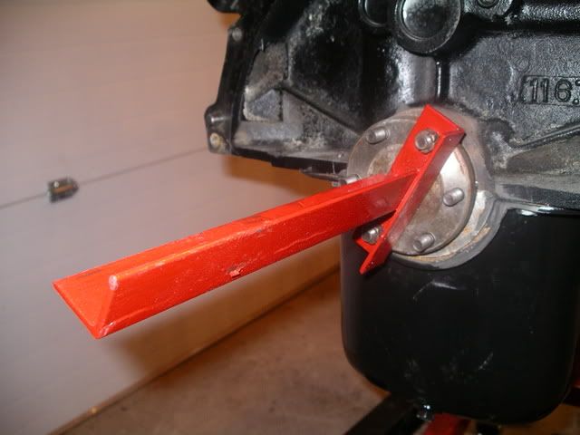
    I've never dialed in a bell housing before but with a little advice, I successfully accomplished the procedure. I started out building a tool from Bob Johnstone's Avanti page and mounting it to the crank.


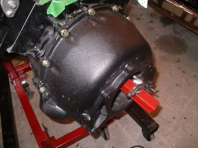
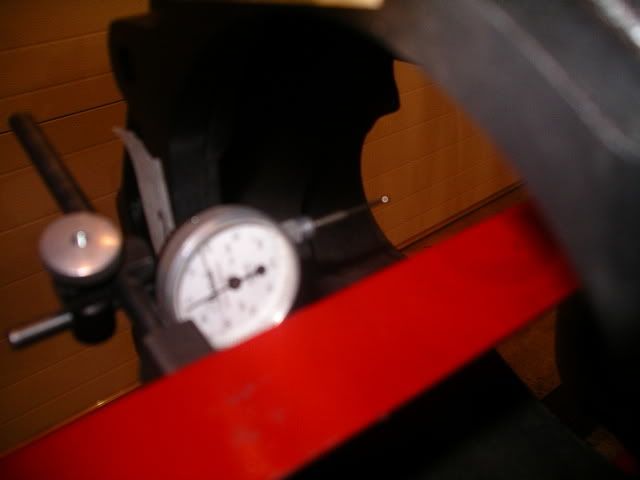
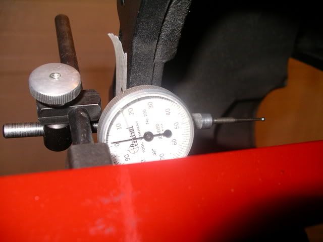
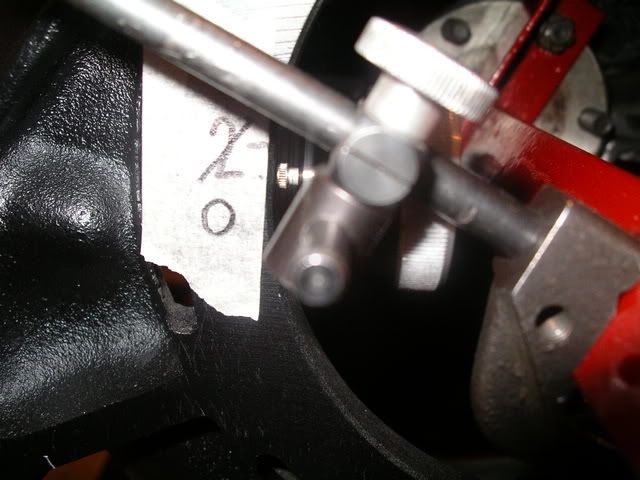
    I pulled the existing dowel pins and mounted the bell housing just firmly with all the bolts to the block. I then Mounted the dial indicator to the new tool and set the reading about half way through the throw of the indicator then setting the reading to 0. This will allow a Positive and Negative reading.


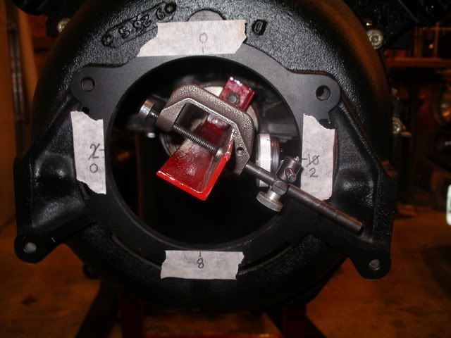
    You should know this is a two person procedure or you will be running back and forth, up and down a lot. My Son was turning the crank bolt while I was taping numbers to the quadrants at 12:00, 3:00, 6:00 and 9:00 o'clock positions


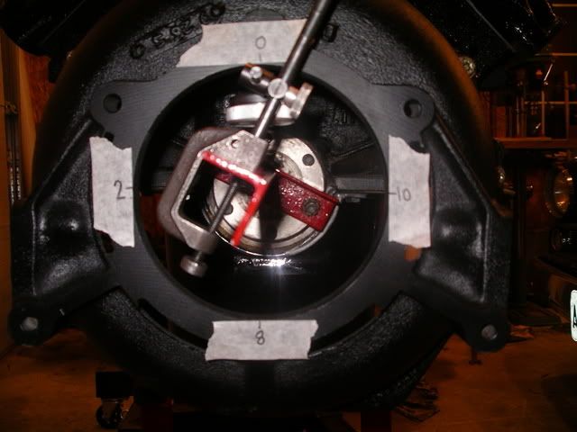
    If 12:00 o'clock is dialed in to "0" and 6:00 o'clock is "8" the bell housing needs to shift .004 down splitting the difference between the two points

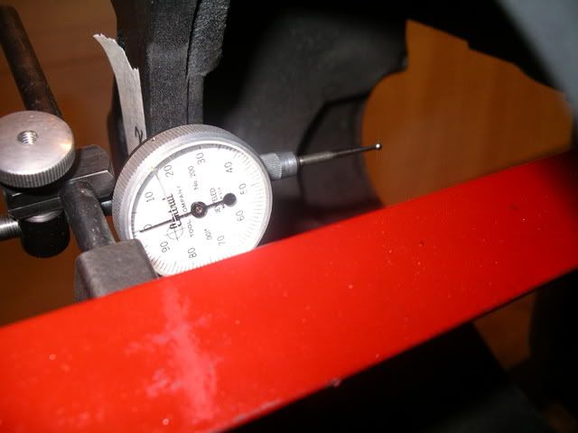
    The indicator reads at 9:00 o'clock "2" and 3:00 o'clock reads "10" which is .008 between them and needs to be shifted .004 to the right.


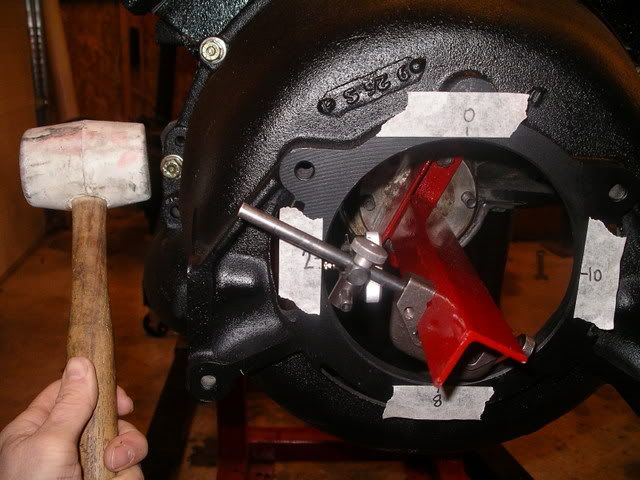
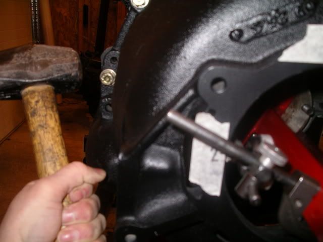
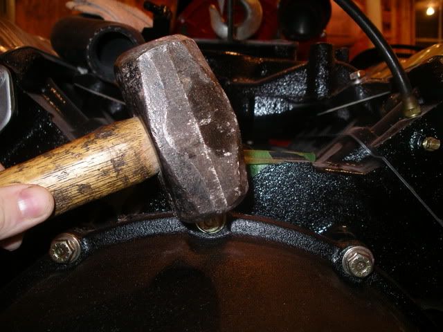
    The rubber mallet did not work for me and just bounced off no matter I hard I hit it so I got out the big gun and tapped it to the right with ease. Just a light tap


    Check the reading again. I managed to bump it .004 to the right


    Well I should have the bell housing on the horizontal pretty well centred. Dial it back to zero and check it.


    Remark the tape to "0" and Move the crank to 3:00 o'clock


    check the reading and mark the tape '2' I am now out .002 from 9:00 o'clock


    Move to the Vertical. We know we are out .004 from the top so give it a bump down


    At this point I re-taped all quadrants and set the dial indicator at the 12'clock position. After bumping I tightened the bell housing down Dialed in 12:00 o'clock to zero I took readings again.

    12:00 - '0' 3:00 - '-1' 6:00 - '-4' and 9:00 - '-4'


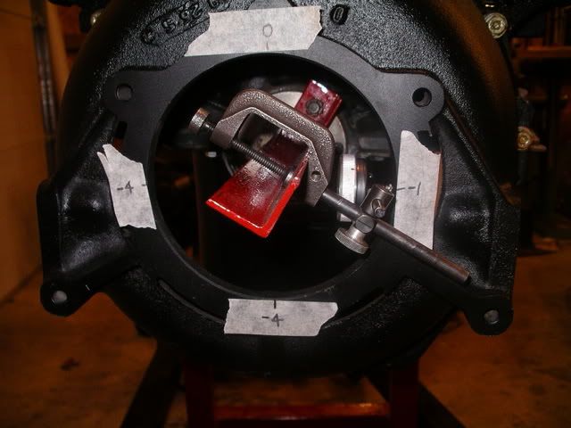
    On the vertical I am out .004 and within tolerances on the horizontal I am out .003 and within tolerances too.

    I checked it again and decided this was good enough. I located my 3/8 dowel pins I purchased at my local industrial supplier and a slightly smaller sized drill bit and re-drilled the existing 5/16" holes for the 3/8" dowels.

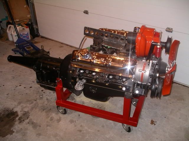
    The entire process took my son and I about 2 hours last night to dial in the bell housing. It allow me to install Flex plate, torque converter, and transmission today


    One thing in my mind remains unanswered, I have the Bell housing centered to the crank and there is no tolerances between the flex plate and the crank. but there seems to be tolerances between the torque converter and the flex plate. The manual uses a special "J- tool" I don't have the number right now but that "J series tool" aligns the torque converter to the flex plate by attaching to the Bell housing and to the torque converter then you turn the engine over twice and tighten the flex plate bolts.

    I am thinking I could accomplish the same thing by mounting the transmission
    1964 GT Hawk
    PSMCDR 2014
    Best time: 14.473 sec. 96.57 MPH quarter mile
    PSMCDR 2013
    Best time: 14.654 sec. 94.53 MPH quarter

    Victoria, Canada

  • #2
    GREAT job![8D] Did it just right. Nice pictures, this help out a lot of people who need to do it but have no idea how to get a "J-tool."

    You are right about the T/C to flex plate "alignment." Really it's just letting the torque converter find it's "natural centering spot" between it's pilot stub to the crank pilot hole and the T/C bolts to the flex plate. You want to do this to prevent any awkward angle that could have happen during install -if not corrected before start up you can break a flex plate or worse something farther down the line.

    Rotate twice and then snug it up.

    Best Regards,
    Eric West
    "The Speedster Kid"
    Sunny Northern California
    Where the roads don't freeze over and the heat doesn't kill you.
    And an open road is yours to have -only during non-commute rush hours 9am-4pm and 7pm to 7am (Ha, ha, ha)
    55 Speedster "Lemon/Lime" (Beautiful)
    55 President State Sedan (Rusty original, but runs great and reliable)

    Comment


    • #3
      In Group IV on page 57 of the Shop Manual in the Flightomatic Section they refer to the J-6310 Converter Aligning Tool. Figure 78 shows the tool bolted to the Bell housing. Could have used one of them today.


      1964 GT Hawk R2 Clone
      Oakville, Ontario.

      Hamilton Chapter
      See you at Niagara 2008 Crossroads Zone Meet July 18-20
      1964 GT Hawk
      PSMCDR 2014
      Best time: 14.473 sec. 96.57 MPH quarter mile
      PSMCDR 2013
      Best time: 14.654 sec. 94.53 MPH quarter

      Victoria, Canada

      Comment


      • #4
        I don't understand all this. Back in the early 60's I changed a 1957 Golden Hawk from an auto to a 4-speed.I put a 61 4-speed housing and a B-W 4-speed in it and had no problems . Was I just lucky ?

        1961 Hawk 4BC,4-SPEED,TT

        Ken Byrd
        Lewisville,NC
        1961 Hawk ...4-Speed;4bc;Twin Traction

        Ken Byrd
        Lewisville,NC

        Comment


        • #5
          I would like to extend my sincere thanks for sharing this! As much as I've heard the procedure described, for some reason I just could not get my mind around it... but your tutorial finally helped me understand it! I've done probably hundreds of bellhousing/trans. installs on Big 3 vehicles, and have never heard of the need to dial one in, or ever had a problem. Leave it to Studes[)]

          Not only was your work great, I know how much effort it takes to upload pictures to a host site, write the thread copy, and insert the pics...

          Thank you again for sharing this- I'm going to print out several copies and keep it in all my shop manuals!


          Robert (Bob) Andrews Owner- Studebakeracres- on the IoMT (Island of Misfit Toys!)
          Parish, central NY 13131


          Comment


          • #6
            I wonder what they did at the factory. I can't believe they went through this whole time-consuming procedure with every engine-bellhousing pair they assembled. I wonder if they has a fixture that could be easily clamped onto the crank flange to center the bellhousing?

            BTW, for any of you who are rebuilding an engine to go with a new (to it) bellhousing, the time to do this job is when the crank is in the block, but before the rods and pistons are installed. So, so easy to turn the crank then!

            Gord Richmond, within Weasel range of the Alberta Badlands
            Gord Richmond, within Weasel range of the Alberta Badlands

            Comment


            • #7
              Allen, that's great! The first really good illustration of the steps needed that I've seen anywhere. Thank you very much!


              [img=left]http://members.cox.net/clarknovak/lark.gif[/img=left]

              Clark in San Diego
              '63 F2/Lark Standard

              The Official Website of the San Diego Chapter of the Studebaker Drivers Club. Serving San Diego County

              Clark in San Diego | '63 Standard (F2) "Barney" | http://studeblogger.blogspot.com

              Comment


              • #8
                The car manufacturers do have the equipment to more quickly center the bellhousing - but that doesn't mean they would dial it in as nicely. A well centered bellhousing is more noticeable on a manual trans than an automatic. On manual trans cars a correctly centered bellhousing makes for noticeably slicker shifting, an off center bellhousing can makes shifts feel awful and slow because of the side pressure to the trans mainshaft. Most people get lucky enough when swapping transmissions, or they just accept a crappy shift quality that could have been improved by dialing in the bellhousing.

                There is another alignment that should be checked at the same time: how true and perpendicular the trans to bellhousing mounting surface is to the crankshaft centerline. Just move the dial indicator to the mounting surface to check for runout. It is exceedingly rare to have a runout issue on the mounting surface - but factory machining mistakes can happen.

                Thomas

                Thomas

                Long time hot rodder
                Packrat junk collector
                '63 Avanti R2 4 speed

                Comment


                • #9
                  quote:Originally posted by blackhawk61

                  I don't understand all this. Back in the early 60's I changed a 1957 Golden Hawk from an auto to a 4-speed.I put a 61 4-speed housing and a B-W 4-speed in it and had no problems.
                  That's what I'm saying! With all the high-RPM race cars and super expensive racing engines I've driven, I've never done this, or ever had an engine or trans. expert ever even recommend it, let alone say it was required...?

                  I just assume it's a Studebaker thing, due to less strict casting/machining standards...

                  Robert (Bob) Andrews Owner- Studebakeracres- on the IoMT (Island of Misfit Toys!)
                  Parish, central NY 13131


                  Comment


                  • #10
                    Allen-
                    Great post!
                    Verrry nice engine dolly too..!
                    I'm currently looking to make something up and yours really caught my eye!

                    Best Regards- Matt

                    1963 GT Hawk
                    1960 Metropolitan Convertible
                    1972 AMC Javelin/ AMX
                    1958 Cushman Eagle
                    -Matt

                    1963 GT Hawk
                    1960 Metropolitan Convertible
                    1972 AMC Javelin/ AMX
                    1956 Cushman Eagle

                    Comment


                    • #11
                      Add my name to the list of "students" who really appreciate such clear and precise instructions and pictures.

                      Comment


                      • #12
                        Great to see this tutorial. Have heard about it for years, and now it makes sense. Eliminating vibration, no matter how minute, is important, especially at high rpm. How did you check the "trueness" of the fixture that the dial indicator is sitting on?

                        Comment


                        • #13
                          Allen, where is the dial indicator making contact? At the back side of the dial?

                          [img=left]http://simps.us/studebaker/misc/images/Avacar-hcsdc.gif[/img=left]
                          Paul Simpson
                          "DilloCrafter"

                          1955 1/2 Ton Pickup
                          The Red-Headed Amazon
                          Deep in the heart of Texas

                          Paul Simpson
                          "DilloCrafter"

                          1955 1/2 Ton Pickup
                          The Red-Headed Amazon
                          Deep in the heart of Texas

                          Comment


                          • #14
                            It seems whenever this procedure is described after going to great detail on the dial-in procedure everyone just says: "drill the dowel holes larger with the drill".
                            For me that has always been the hardest part on all of the ones I have done. It is way harder than it sounds. There is no flat surface to "guide on" and no room for a drill guide to drill the hole STRAIGHT!

                            It makes sense to do as the manual says and let the thicker half do the guiding, which is the block and hopefully the drill will make a new hole in the bellhousing without following the existing center of the old hole making for a crooked hole. It is also difficult to get a drill in there depending on the completeness of the engine assembly.

                            Some I have done I avoided this problem completely by drilling new holes in the blank areas next to the old dowel holes.

                            StudeRich
                            Studebakers Northwest
                            Ferndale, WA
                            StudeRich
                            Second Generation Stude Driver,
                            Proud '54 Starliner Owner
                            SDC Member Since 1967

                            Comment


                            • #15
                              This is a great contribution. Many thanks for the extra effort and time that went into the tools and the pictoral.
                              As an aside, I always wondered if instead of replacing those large dowel pins, whether it would be acceptable to drill a series of smaller holes and use a decent sized roll pin. It's the bolts that hold it in position and the dowels only keep it in the sweet spot, until you tighten everything up..

                              Bob Johnstone
                              64 GT Hawk (K7)
                              1970 Avanti (R3)

                              Comment

                              Working...
                              X