Announcement

Collapse
No announcement yet.

Aren't all OD relays created equal?

Collapse
X
 
  • Filter
  • Time
  • Show
Clear All
new posts

  • Aren't all OD relays created equal?

    I fried the electrical components of my overdrive a couple years ago. Its a long story, but trust me, lessons were learned. Anyway, I have been patiently scouring eBay and accumulating parts for the overdrive. I have:
    1. Replaced the kickdown switch with a new one
    2. Replaced the reverse lockout switch with a new one
    3. Rewired the entire car
    4. Bought a working, used solenoid
    5. Attempted to rebuild (apparently unsuccessfully) the OD relay as a solid state unit, using instructions found on the SDC website.
    6. When that didn't work, I bought a used, supposedly NOS (although I doubt it) supposedly 6 volt OD relay that is supposed to be a 6 volt Nash unit. I thought that I understood that Nash OD units were also made by Borg-Warner.


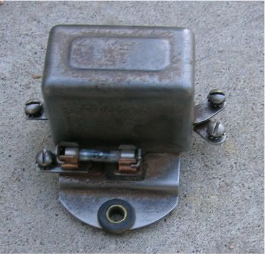
    Today, I went out to install this Nash OD relay (it has a stamped logo "RBM Made in USA") on my car. The terminals are different than my old one. Instead of "sol", Ign', etc. they are labeled (Clockwise, starting in upper right) 2, 1, 3 (fuse), L. I worked on the apparently incorrect assumption that the wiring positions were the same as my old one and hooked up ignition wire to #2, solenoid to #1, battery to #3, and kickdown switch to L.
    I went out to test it on the car. When I got up to 30 MPH, the ampmeter pegged to charge and the fuse on the relay blew. I slowed down, disengaged the OD, and everything returned to normal.
    My questions are these:
    1. How can I determine the correct wiring configuration for this relay?
    2. How can I test the relay to be sure it works, off of the car?
    3. Will this "off brand" relay work with my OD?
    4. Could having the case grounding out be a problem? This relay has rubber grommets that I assume are intended to electrically isolate the case from the firewall. The Stude relay has no such insulators.
    5. Is there any way, short of buying a new relay for $95+, that I can be sure that the relay really is the (only) problem with this system?

    Oh and by the way, I have a used 12 volt Studebaker relay that I stashed away, anticipating that I might use it if/when I switch over to 12 volts. Can it be of any use to me in my current 6 volt configuration?

    Advice, enlightenment, even smart-ass remarks, would be appreciated.
    John
    1950 Champion
    W-3 4 Dr. Sedan
    Holdrege NE

  • #2
    By any chance is the car's battery hooked up with the engine ground cable to the battery negative post?
    Restorations by Skip Towne

    Comment


    • #3
      Have you got a multimeter? I'm referring to the 2R truck shop manual, here, and it does not indicate a ground is necessary for the relay.

      The terminal with the fuse is obvious, it goes to the hot side of the battery, probably picked off at the starter solenoid.

      Of the remaining three terminals: put your multimeter on its lowest ohms scale, and probe various pairs of terminals. Only one pair should show any continuity if the relay is sound, and if it is wired like the stock Stude one. That pair should show maybe between 20 to 60 ohms resistance, at a guess. The resistance of the relay coil. Mark those two. Now, with a good fuse in the holder, connect your meter probes to the other two terminals, and use clip leads to connect the two marked terminals to a six-volt battery. You should hear the relay click, and the ohmmeter should read close to zero ohms.

      None of the terminals should show continuity to ground at any time. If any do, the relay is either faulty, or not compatible with the Stude wiring scheme.

      You could also simply remove the cover from the relay, and eyeball which terminal is connected to what.

      What connects where: the terminal with the fuse goes to the hot side of the battery. Its counterpart, the one that gets continuity with the fused terminal when the relay clicks on, goes to one of the screws on the solenoid; I think it's marked with a numeral 6, but I don't remember for certain. What I am sure of, is that if you get the two screws on the solenoid wired wrong, nothing bad will happen, the overdrive just won't work. No smoke will come out. Of the remaining two, the two that connect internally to the relay coil, one goes to a terminal on the kickdown switch, one of the pair closest to the plunger. The other goes to the "gage" terminal on the ignition switch, or "accessory" if so marked. All it really needs is a source of 6 volts that goes off when the key is off. It shouldn't matter which of this pair is used in which role, the relay coil ought not to be polarity-sensitive. For what it's worth, the wiring diagram shows the terminal on the same end of the relay as the fused terminal as going to the kickdown switch, but it's a schematic diagram, which means that it may not exactly represent the physical arrangement of terminals on any given component. (Modern relays may have diodes shunting their coils, and may be polarity sensitive, but silicon diodes didn't exist when these puppies were made.)

      Going further: we've dealt with one of the 4 terminals on the kickdown switch. The other one on the "close" side to the plunger connects to the lockout switch on the rear of the transmission, and the other terminal of the lockout switch connects to the governor. When cut-in speed is reached, the governor makes a ground, and that ground is passed through the lockout switch, through the wires, and through the kickdown switch to one end of the relay coil. Since the other end of the coil is "hot" via the ignition switch, the coil becomes magnetized and pulls in the relay armature, closing the circuit between the battery and the OD solenoid.

      What about the other two terminals on the kickdown switch, the ones on the "far" side from the plunger? One of them goes to the other terminal on the OD solenoid, and the other goes to the ignition points or to the "points" side of the coil. The "other" terminal on the solenoid has the property of going to ground whenever the solenoid is energized. In all normal driving, the two terminal on the "near" side of the kickdown switch are always connected, and the two on the "far" side are not connected. Only when the accelerator is floored do things change. In that event, the two on the near side are disconnected, which deprives the OD relay of its ground, causing the relay's contacts to open, thereby interrupting power to the solenoid. At the same time, the two on the "far" side are connected together, which serves to connect the ignition points to ground via the grounding contact within the solenoid. That momentarily kills the spark, and the engine quits making torque for a fraction of a second. That's enough to unload the gears in the overdrive, and the spring in the solenoid withdraws the plunger, and shifts the unit to direct drive. As the plunger withdraws, the grounding contacts open, and the ignition begins working again, even though your foot is still on the floor.

      It sounds like somehow the way you had it wired, the relay created a short to ground when it kicked in. The fact that it apparently did kick in when you reached 30 mph tells me you at least got the relay coil terminals connected right. Maybe that relay is in fact grounding through its case.
      Gord Richmond, within Weasel range of the Alberta Badlands

      Comment


      • #4
        Note that with those bushings inside of the mounting grommets, the unit will be grounded through the screws to fender, but as Gord said, it is not necessary to be grounded if the relay is wired for a Studebaker.
        StudeRich
        Second Generation Stude Driver,
        Proud '54 Starliner Owner
        SDC Member Since 1967

        Comment


        • #5
          Rich, I think the bushing-inside-the-grommet arrangement will cause the regulator body to "float" in the rubber grommets and not be grounded. A separate jumper wire from the mounting screw to the regulator body would be required to ground the regulator body if the other mounting tabs have similar grommets. BP
          We've got to quit saying, "How stupid can you be?" Too many people are taking it as a challenge.

          G. K. Chesterton: This triangle of truisms, of father, mother, and child, cannot be destroyed; it can only destroy those civilizations which disregard it.

          Comment


          • #6
            Gord
            Thanks VERY much for your enlightening explanation. I can now test my relay to see if it is working as advertised. Your explanation of how the overdrive electrical system works is also vey easy to understand and very helpful to me. You are a great asset to this forum.
            Dwain
            Thanks for your help but, yes, I understand that this car has a positive ground electrical system.
            Rich
            The rubber grommets on this relay case do have brass inserts, but they don't touch the case, so I think that the case is effectively isolated from ground, if installed properly.

            Thanks to all of you for your interest in my problem, and your willingness to help.
            John
            1950 Champion
            W-3 4 Dr. Sedan
            Holdrege NE

            Comment


            • #7
              Lothar, I think I know what happened. I think you have terminals 2 and 1 interchanged (per your description). Wired that way, the relay coil would "see" a ground via the solenoid's heavy-wire pull-in winding, and the relay would close at any time the ignition is on. The solenoid would not engage, howver, since the relay coil would not pass anywhere near enough current to let it operate. And the wire from the "cold" terminal of the relay's contacts now goes, via the kickdown and lockout switches, to the governor. So, hooked up, as you describe, nothing happens until you reach 30 mph, then the governor clicks in, and that poor little fuse is trying to feed a dead short to ground, and it pops.

              If you've done nothing else since, swap the wires on #1 and #2, and you should be good to go.
              Gord Richmond, within Weasel range of the Alberta Badlands

              Comment


              • #8
                Originally posted by Lothar View Post
                Thanks for your help but, yes, I understand that this car has a positive ground electrical system.
                I asked because of a line in the first post, "the ammeter pegged to charge".
                Restorations by Skip Towne

                Comment


                • #9
                  Thanks, Gord. I'll try swapping the wires next time I get the car out. I disconnected the relay after things went wrong yesterday. I think that my Studebaker will be hibernating for at least a couple weeks now that a cold front has blown into town.
                  I took my little boy Joe (pictured in my avatar) along yesterday when I took the Champion over to my storage garage. The "Baker", as he calls it, has a special place in his heart, I think because he associates it with the Hudson in the movie "Cars". I hope we can get a REAL Studebaker in Cars 2. Anyway, he cried hard, with tears running down his face, when it became clear that the "Baker" wasn't coming home with us. He was somewhat consoled by a trip to the Sonic for ice cream.
                  Thanks again for your help.
                  John
                  1950 Champion
                  W-3 4 Dr. Sedan
                  Holdrege NE

                  Comment


                  • #10
                    Dwain, a short to ground on the battery side of the ammeter would peg the ammeter to "charge". The generator and regulator would "see" a dead battery, and go to max output.
                    Gord Richmond, within Weasel range of the Alberta Badlands

                    Comment

                    Working...
                    X